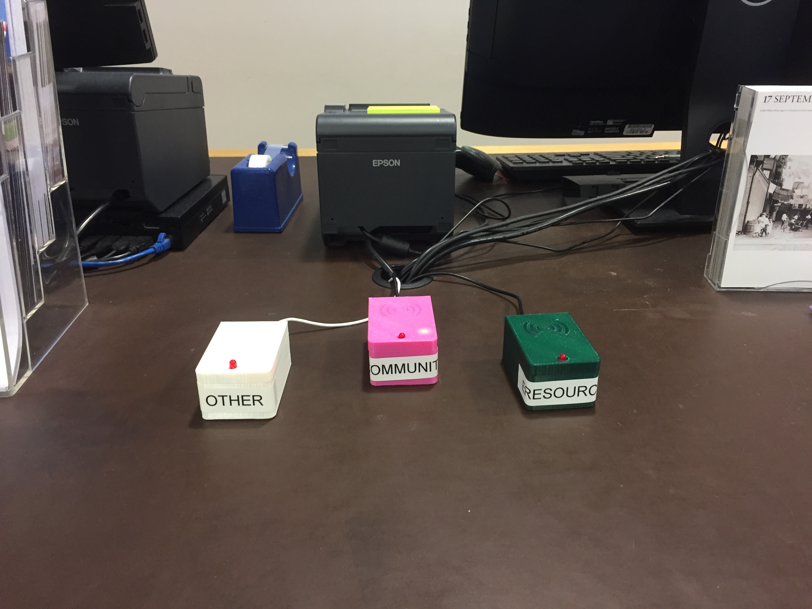
DoDeDoDo (Production)
It’s been several months since I posted up my prototype of an RFID based library reference tracker that I lovingly called the ‘DoDeDoDo’. Since then I’ve worked through several variations of case design, code, and wiring. I even added a blinky light to it! I feel now that it is fit for reproduction and have ironed out the many, many bugs that came with not really knowing what I was doing. I still don’t but I’ve learnt a lot along the way. If you are looking to replicate this system and roll it out in your library (or other location) use this updated documentation and follow my GitLab for updates.
Component List
Creating one DoDeDoDo box will require the following:
- nodeMCU
- RC522
- Socket-to-socket Dupont connectors x9
- 5mm LED x1
- 200 ohm 0.5 watt resistor x1
- USB to Micro-USB cable
- Micro-USB Switch (optional)
- USB Power supply (phone charger)
- 3D Printed Case
- M3x6mm Screws x10 (I actually only used 5 per case to be cheap)
- RFID Cards/Fobs (enough for one per staff member)
Other
- Soldering station
- Computer with Arduino installed
- A Google Account
- A Pushingbox account (see setup)
Total cost for one DoDeDoDo is just under $50.00 AUD, assuming purchasing individual power supplies, and access to a 3D printer for zero cost. If you remove the power supply cost, they work out to around $28 each, less if you have spare USB cables around.
Pro tip: check your library's lost & found as a good source of free USB chargers ;)
Setup
This setup will run you through creating a Google Form and Sheets, connecting it to a Pushingbox account, and linking them to a physical nodeMCU+RFID system.
Step 1: Create a Spreadsheet
Firstly you need to setup a Google Form and Sheet. Log into your Google Drive account and create a spreadsheet and name it something relevant ‘DoDeDoDo – Library Branch’.
Step 2: Create a Form
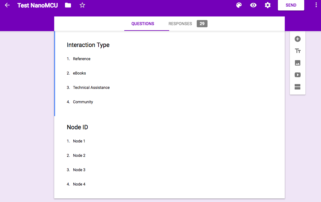
Create a new Form and name it after the sheet. Create a ‘dropdown’ question box and enter in your interaction type data. For Western Australian public libraries this is where we would enter in our five types of enquiry.
Create a second ‘dropdown’ question box and call this ‘Node ID’ and enter in the names of each node. This could be ‘Node 1’, ‘Node 2’, ‘Node 3’, etc. or something location based like ‘Public PCs’, ‘Photocopier’, or ‘Adult Non-Fiction’. Alternatively, you could label each node something unique like ‘SurfKing’.
Since I'm running DoDeDoDo across three library branches I want to know which branch is sending the stat. I added a third question with the names of the library branches.
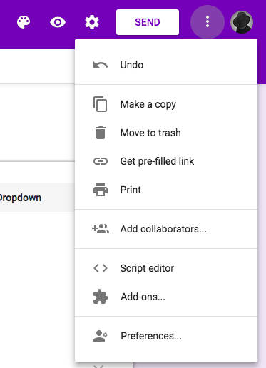
Step 3: Get the entry fields
Once you’re happy with your form, click the three dots menu on the top right and select ‘get pre-filled link’. This will take you to an entry view for your form, here you can set pre-filled responses (which you could easily turn into a one-click link for a web only version of this project for back-of-house staff).
Fill in the form with any response ie. ‘Reference’ and ‘Node 1’ and click the ‘GET LINK’ button. Paste the now copied link into a note pad as we are going to pull out two pieces of information from it.
It should look something like this:
https://docs.google.com/forms/d/e/1FAIpQLScKRqbOYnAACG9vyyWqPQiwuviTqiUrmvI5BfNZcwGq2A2OSA/viewform?usp=pp_url&entry.1927206069=Reference&entry.1745966778=Node+1&entry.1855798778=Armadale
We are interested in the parts after ‘viewform?’
viewform?usp=pp_url&entry.1927206069=Reference&entry.1745966778=Node+1&entry.1855798778=Armadale
Our first input field is called ‘entry.1927206069=’, the second ‘entry.1745966778=’ and the third 'entry.1855798778=Armadale'. This is what our nodes will be sending data to. Keep these fields aside, and the original URL, as we will be using them later.
NB: you could easily have more than three fields, they will just append to that url. This means you could have a node name field with a location field meaning you can move nodes around without having to rename them.
Step 4: Pushingbox
Go to pushingbox.com and login with the same Google account you used to setup the Sheet and Form.
Once logged in go to ‘My Services’ and ‘Add a service’, and select ‘CustomURL’. This is setting up the base URL of the GET request.
Name the service something like ‘DoDeDoDo’ and for the Root URL field copy in your pre-filled form URL up to the ‘viewform?’. You then need to replace ‘viewform?’ with ‘formResponse’.
Eg.
https://docs.google.com/forms/d/e/1FAIpQLScKRqbOYnAACG9vyyWqPQiwuviTqiUrmvI5BfNZcwGq2A2OSA/formResponse
Leave the method field as GET.
Save and go to ‘My Scenarios’. This will now setup the data variables.
Enter a name for the scenario, I used ‘DoDeDoDo’ to keep everything consistent, and then click ‘Add’.
Click ‘Add an Action’ and select ‘Add and action with this service’ on the service you just setup (in my case it was ‘DoDeDoDo’).
In the Data field you need to add in those field names we saved earlier. It should look something like this:
?entry.1927206069=$query$&entry.1745966778=$node$&entry.1855798778=$branch$
If you have other fields append this with $entry.###########=$<field name>$ .
You’ll notice that we’ve changed our responses from ‘Reference’, ‘Node+1’, and 'Branch' to ‘$query$’, ‘$node$’, and '$branch$'. These are now variables that we will set in the nodeMCU code. This will allow us to set up multiple nodes sending different responses via the same API call. You’ll see this in the code below.
Once you’ve setup the Scenario you’ll be presented with a deviceID which appears next to the Scenario name. Save this for later.
That’s it for the hard stuff, now onto programming our nodeMCU.
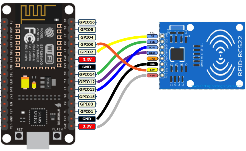
Step 5: Hardware
Follow the wiring diagram and make sure you have your RC522 and nodeMCU connected before uploading the code. If you change the SDA (SS) and RST pin locations make sure to update the definitions in the code.
| nodeMCU Pin | to | RC255 Pin |
|---|---|---|
| D3 | RST | |
| D4 | SDA | |
| D5 | SCK | |
| D6 | MISO | |
| D7 | MOSI | |
| GND | GND | |
| 3.3V | 3.3V |
LED
I have added a 5mm LED for feedback when not attached to a serial reader. This is important and gives staff instant feedback that the device is working/not working.
| nodeMCU Pin | to | LED Pin |
|---|---|---|
| D1 | -200 ohm resistor- | Positive + |
| GND | Negative - |
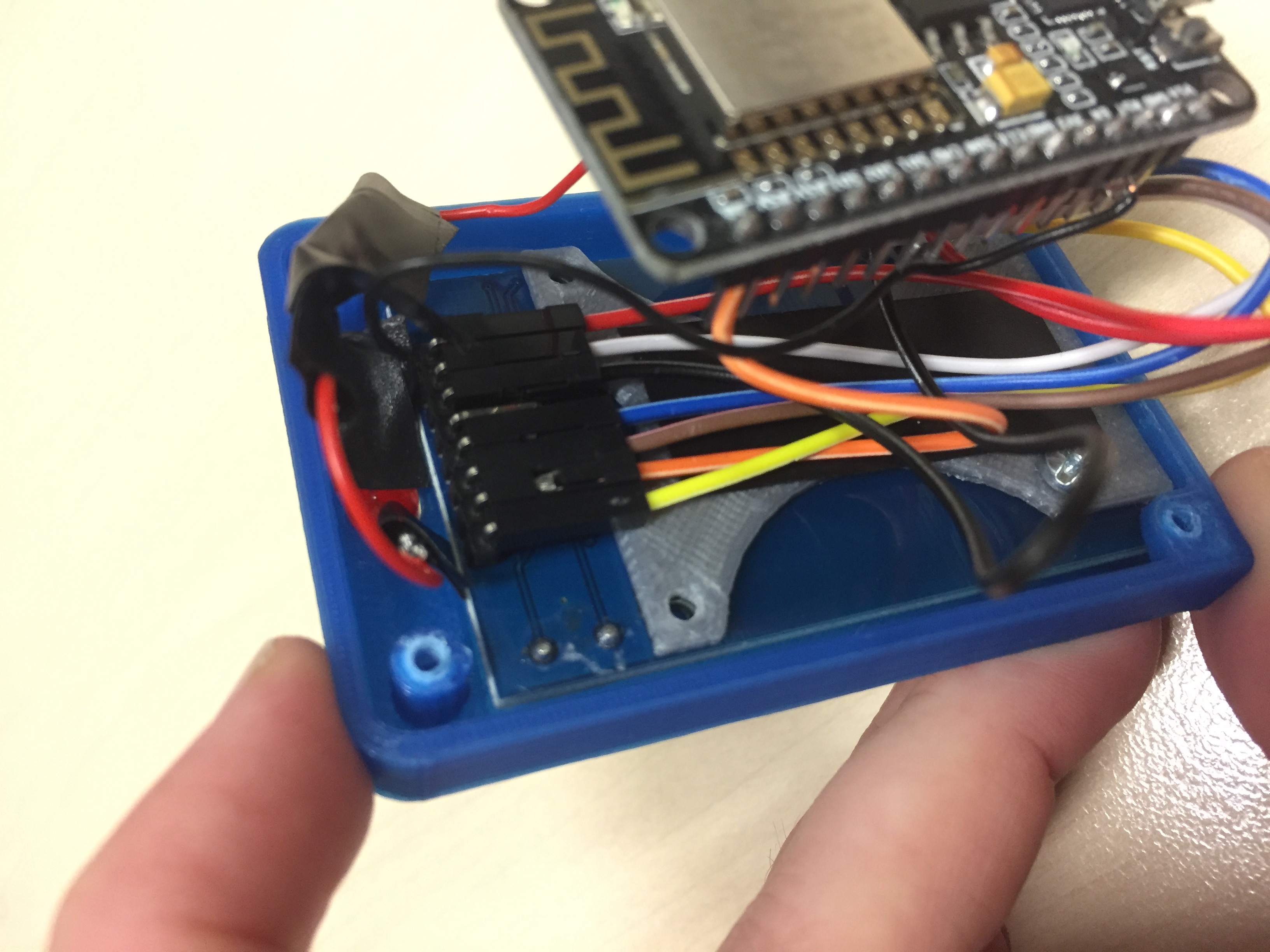
Pro Tip: I originally soldered all the connections but was shunned by a friend who suggested that I simply solder a 90 deg header onto the RC522 (mine came with these) and use socket-to-socket dupont connectors. This resolved a lot of issues I had with bad connections and made creating seven (soon to be fourteen) of them much easier! I did solder the LED as it kept slipping off the connectors but I’ll re-attempt this with dupont connectors for the next two batches I need to make.
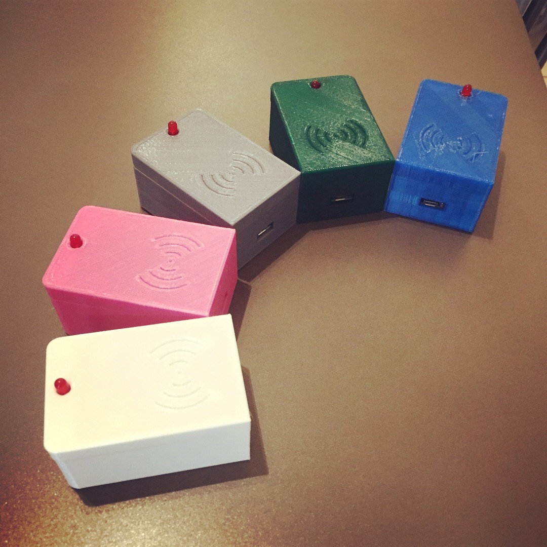
Step 6: Case
Download and print the DoDeDoDo case from Thingiverse and mount the nodeMCU upside down at the bottom of the case. The wifi card will be facing down if mounted correctly. I found that the RC522 caused some interference with the wifi signal and figured better to be safe than sorry. Plus placing it upside down will allow enough room for the the dupont connectors.
Secure the RC522 on the lid of the case and screw both halves together.
Step 7: Code
Once you have your hardware sorted you will need to download the Arduino IDE.
After installing you will need to setup for the nodeMCU board. Open the IDE and:
- Select File and then click on Preferences.
- In the additional Boards Manager URLs add the following link http://arduino.esp8266.com/stable/package_esp8266com_index.json
- Click OK and then navigate to Tools - Boards - Boards Manager
- In the search field type esp8266 > click the esp8266 by ESP8266 Community - Click Install
- The ESP8226 library has been added.
Note: I was using a Mac and had to install a driver to get my board to show up. Check the chip (tiny black square near the USB port) on your nodeMCU and if, like mine, it says CP210x you need to download and install this driver, otherwise there is a signed Mac OS CH340 Winchiphead driver out there.
Now you need to install the RFID library for MFCR522 created by Miguel Balboa. Download the library as a .zip file and import it into Arduino IDE.
With all those dependencies installed you can now open a new Sketch in Arduino and copy the code from the GitLab repository.
Step 8: Variables
In the above code there are several variables you need to change.
Wifi Settings
const char* ssid = "SSID Name"; const char* password = "WIFI Password";
Replace ‘SSID Name’ and ‘WIFI Password’ with the SSID and password of your wifi.
Note: the nodeMCU is limited to 2.4Ghz. I had to have this enabled on our router as we only had 5Ghz channels.
Pushingbox Settings
This block creates the GET URL to send to Pushingbox which then enters the data into the Google sheet.
const char* devID = "Pushingbox devID"; const char* query = "Query Type"; const char* node = "Node Name"; const char* branch = "Branch";
Enter your DeviceID from pushingbox and then use the ‘&query=’ for your query type, ’&node=’, and ‘&branch=’ if you set one up (you can delete the branch if needed, just remember to delete it from the string section of the code).If you have spaces in your node name, branch, or query type use '+' instead of space ie. 'Surf+King'.
As we used a dropdown menu on our Google Form make sure you use the exact wording on the form. Alternatively you could have used a free text field but I like a controlled vocabulary.
That’s it. Compile and upload your code to the nodeMCU and the blue light on it board should light up once connected to the wifi (some of mine flash constantly, others stay on solid).
The LED should light up and will go out briefly when you pass an RFID tag in front of the reader, this is the nodeMCU sending the data to the spreadsheet. Check the serial monitor on the Arduino IDE (with the board connected) and it should output the pushingbox URLs on each successful tag. You can then see the result in your Google sheet logging date, time, query type, and node name.
If the GET Request or wifi connection fail for any reason the LED will blink twice quickly, and you will see an error in the serial monitor.
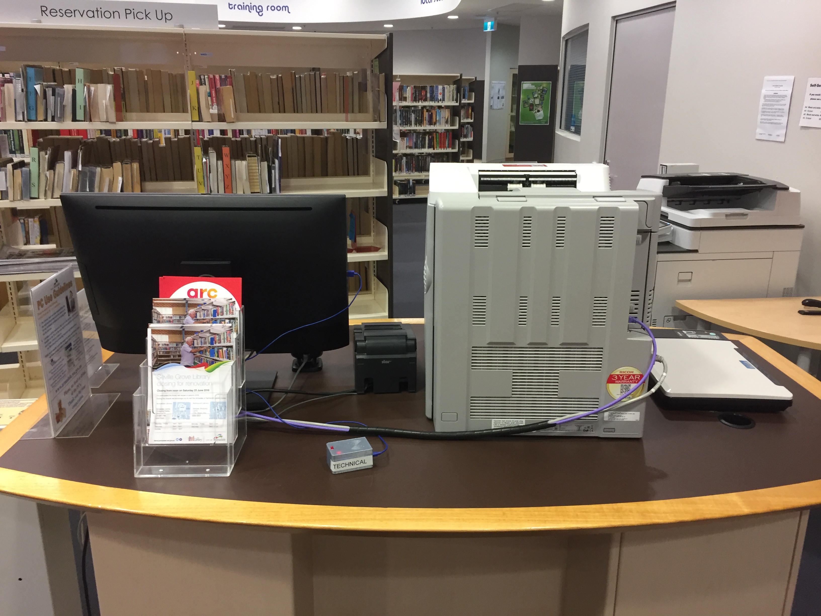
Deploying
Once you have one working then create as many as you need. I have several nodes running the same query (Technical) and have placed them in the two areas that they are needed. Make sure to power these devices using a USB power adapter capable of at least 1A (the type used to charge mobile phones are great), as the nodeMCU and RC522 can draw more power than the standard USB ports on PCs.
I’ve looked at but haven’t implemented a battery system so you could always attach an ESP32 for Wemos Battery Charge Shield v3 Micro USB and place them in areas without power. A learned friend suggested that you “use a 18650 battery the same battery type that are used in laptops, Tesla model S, and those annoying e-cigarettes”. Don't forget to invest in a charger for them.
I also run the web based version of the software DoDeDoDo Web for staff out in the workroom answering phones. With both systems running we cover a wide range of queries and our statistics have become a lot more accurate.
That’s It
If you’ve been able to follow my instructions I’d love to hear from you! (Tweet or toot me, or if something goes wrong I’ll try and help as best I can.
Build, enjoy, and remember “muffins are for customers”.
Written by
What's Next?

A Year In Read-View 2018 (Books)
In 2018 I wanted to read more books, but more importantly I wanted to put more time aside for reading. I managed to get through sixteen titles (three more than last year!), and coupled with the sixty plus comics I read I think I did a pretty good job. 2018 saw a continuation of prioritising women writers (especially in sci-fi) and I continue to have no regrets. This year's reading did however include two of the worst novels I've ever had the displeasure of reading (more on those later), and both

Growth and Ethics
I recently undertook a personal development practice and found out that two of my highest personal values is growth and ethics. It explains why I find people who refuse to learn, or grow extremely infuriating, and reinforced my stance on personal and professional ethics. So when a professional library group in my state decided to invite a speaker that (for me) violates both of those values I was deeply disappointed. More so, the response I got from my objection was met with: "Our belief is that
Don't Make Me Tap The Sign...
Ever since I wrote my 'Do No Harm' post late last year, I've seen a few examples of where this model could be used in GLAMs around the word. I'm not the best at self promotion but occasionally I will see twitter conversations around this topic and drop a link to the model. This is usually met with positive comments but is quickly forgotten. I've been encouraged to write it up properly for something like Lead Pipe so it can get a wider exposure, but that will be a bit of a work in progress at the
Do No Harm
Since I listened to the Incendium Radical Library (IRL) cardiCast episode I can't stop thinking about the collecting policy they have adopted (time stamp 17:49). IRL have broad frameworks they align the library with, so when accepting new donations or looking at acquisitions they look at how these items could harm the wider community and balance that against the good they could do. In Annelise's words: "I guess like the frameworks of this library is social justice, anti-oppression, intersection
We Don't Want Your Donation
GLAM Blog Club's theme this month is Donation which instantly sent shivers up my spine thinking about all the terrible books people bring into the (public) library to donate. As Hugh's example shows, it's often the things we don't put into our collections that make a library. In my own professional life I have seen two types of librarians in regards to donations. One being the accept almost everything librarian, and the other decline's almost everything. I am of the latter persuasion. In one wor
DoDeDoDo Web – Reference STAT(S)!
Back in July I wrote about an RFID location based enquiry tracking system (DoDeDoDo) and two months later I’ve moved on from prototype to production and they are working relatively ok. There are some bugs to work out before I present a new write up and I’ve modified the code slightly to make it easier to troubleshoot and added an LED because blinky lights are awesome. In the meantime I created a locally hosted, web based solution for staff in the workroom that I’m pretty happy with and wanted to

A Year In Read-View 2025
When I write up these reading reflections I always check what I wrote the year before (mostly so I can remember the formatting of these blog posts!). Weirdly, the intro I had been writing in my head for this was almost exactly the same as last year's. I read XX number of comics/books, which was up/down from last year; my novel/non-fiction reading was XX books, up/down from the year before, mostly because my morning reading time on the train has been replaced with writing on the train (mostly); a

A Year In Read-View 2024
I managed to read very nice number of books over 2024, 69 in total. While this is up from the 50 I got through last year, it was interesting to see that the majority of my reading came from graphic novels. This is mostly due to some great titles being available via Hoopla - with the demise of Comixology (and my refusal to help the Amazon juggernaut) I had read fewer and fewer comics over the years, but borrowing them from Hoopla has clearly had an impact. In terms of novels and general non-fict